
Most new applications are built as a single codebase and deployed as a monolith until product-market fit or the need for additional scale is required. Such monolithic applications are easy to write and maintain, and allow you to iterate quickly when there are a smaller number of users and the traffic is low. However, as traffic increases you will need to scale the application to handle the increase in load. One framework for scaling is the “Scale Cube” describe by AKF partners.

The starting point, marked by coordinates (0, 0, 0), represents the least scalable configuration which is the singular, monolithic application deployed on a single server described earlier. Such a design can be scaled “up” by using larger and faster hardware, but it is ultimately limited by the capacity of a single machine. Once you have reached the limits of this design, you can adjust one or more axes of the scale cube to increase the overall scalability of your system.
The scale cube outlines three axes along which an application can be scaled:
- X-axis: Horizontal Duplication
- Cloning or replicating application instances and distributing traffic across them using load balancers.
- Y-axis: Functional Decomposition
- Splitting an application into multiple, independent services based on their functionality (e.g., user management, product catalog, shopping cart).
- This approach aligns with microservices architecture principles.
- Z-axis: Data Partitioning
- Partitioning data based on attributes such as customer demographics or geographic location.
- Each partition can be served by separate instances of the application, allowing for targeted scaling and localized optimizations.
The “Scale Cube” was initially popularized in the book The Art of Scalability, which was released in 2015. Fast-forward ten years and the idea of scaling an application horizontally using commodity hardware could be considered common knowledge for most software engineers, and service-oriented and microservice style architectures are a widely known technique for scaling a system and development team. Scaling along the X and Y axes of the cube have become table stakes for most engineering teams.
So what about Z?
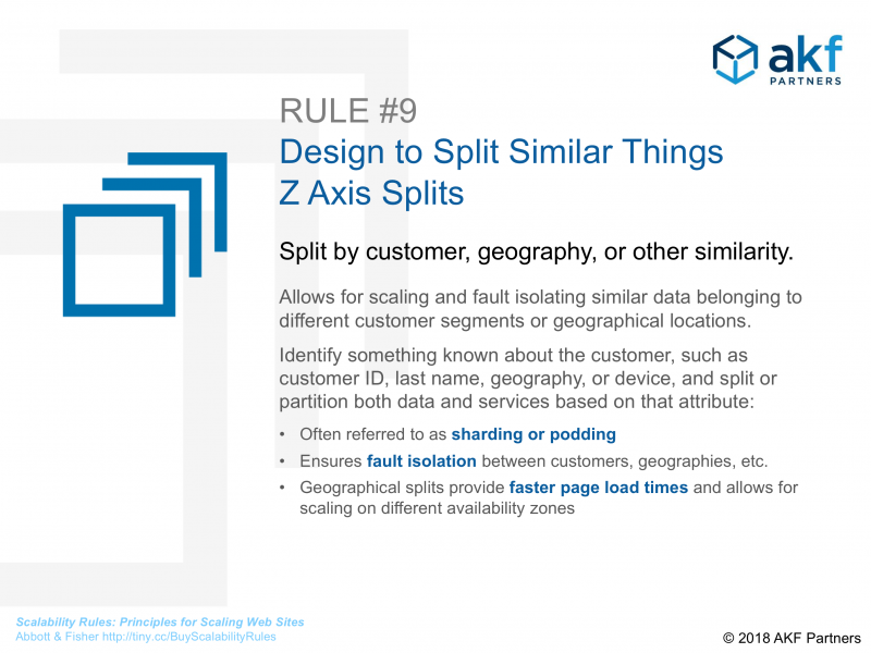
The Z-axis of the cube involves deploying an isolated copy of your complete application that services a subset of requests. For example, all customers in a geographic region, or requests from a particular organization, can be routed to a unique deployment of the application.
Z-axis splits are useful for companies that have already scaled their application by dividing a monolith into services and then scaling those services horizontally, but wish to achieve even greater scale and fault tolerance by deploying isolated instances of their application stack to a subset of customers. While the implementation of Z-axis splits can be among the most expensive, the scalability returns are typically large.
The following diagram from the AKF Partners blog explains how Z-Axis scaling is effective at helping you to scale applications by isolating customers or leveraging geographic replication of data.
Cell-Based Architecture
The Z-scale approach to scaling is also supported by AWS in their well-architected approach called cell-based architecture. Cell-based architecture is a powerful strategy for creating resilient and scalable applications. By dividing your workload into multiple isolated instances called “cells”, you can minimize the impact of failures since each cell operates independently, handling a portion of the overall traffic.
The key components of a cell-based architecture are:
- Cell Router: This lightweight component directs incoming requests to the appropriate cell.
- Cell: A self-contained unit containing everything needed to run a complete instance of your workload.
- Control Plane: Manages administrative tasks like cell provisioning, de-provisioning, and customer migration.
To make it clearer, in the following diagram from AWS guidance on cell-based architecture shows a system deployed as isolated cells alongside a thin layer to route traffic to the right cells. This type of architecture can be zonal or regional, depending on the boundary you define as an individual cell.
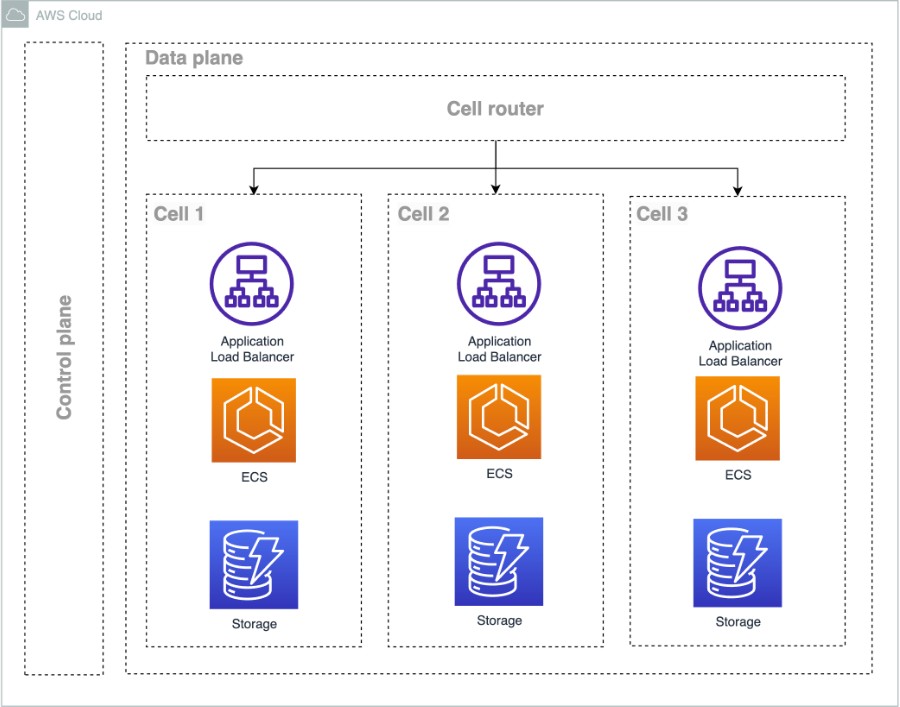
By dividing your system into multiple cells, you gain scale benefits by dividing the workload so that each cell is as performant as possible. As you continue to add new customers, you can provision new cells for them to maintain the performance of existing cells and provide another avenue for scale.
The AWS approach to cellular architecture has a lot of similarities to scaling along the Z-axis of the AKF Scale Cube — we can use the two frameworks interchangeably and the guidance from one reinforces the other. I personally prefer the AWS terms “cell” to the terms “shard” and “pod” used in AKF literature simply because “shard” and “pod” have overloaded meaning depending on the context.
Benefits of cell-based architecture
In addition to the scaling possibilities, there are a number of additional benefits of cell-based architecture, namely:
- Scale-out over scale-up
- Divides the workload such that the load on any component stays bounded over time despite the overall increase in workload
- Lower scope of impact
- Breaking a service up into multiple cells reduces the scope of impact — only the affected cell is impacted.
- Higher scalability using cells as a unit of scale
- Cells provide a way to define known limits and capacity and use those known limits where performance is impact to add new cells to your architecture
- Higher testability of scale and performance
- The capped size of cells allows for well-understood and testable maximum scale behavior. Consistent capped sizes of cells allow a test limit that eliminates the idea that “every day is a new adventure” for teams as they onboard new customers
- More control over deployments and rollbacks
- Cells provide another dimension in which to phase deployments and reduce scope of impact from problematic deployments
- Allows for customer segmentation based on compliance or security
- Possible to segment customers into BYOK or FedRAMP regions (for example, only add new BYOK or FedRAMP customers to the existing us-east-1 cell and do not allow them in other cells)
There is no free lunch
Although Z-axis or cell-based architecture promises near-infinite scalability, it does come with challenges. Particularly, implementing a cell-based system can increase complexity, requiring additional infrastructure and operational overhead to provision, manage, and operate cells. Costs can also rise due to the need for redundant resources and the specialized tools and development required for managing multiple cells. This task is made more difficult if your existing application is complex or consists of multiple microservices — replicating the entire deployment will add considerable operational overhead.
As with any architectural pattern, cell-based architecture isn’t a one-size-fits-all solution. It’s best suited for large-scale, highly available systems where the cost of downtime is significant, and the scaling expectations are large.
I’m excited to see how this pattern continues to develop and how it’s used to build the next generation of resilient applications!