Disaster events are one of the biggest challenges that a software organization can face. Natural disasters like earthquakes or floods, technical failures such as power or network loss, and human actions such as unauthorized attacks can disable an entire fleet of systems, leading to complete failure for a business. To deal with disaster scenarios requires a proactive approach to prepare and recover from failure.
One of the key benefits of running in the cloud is how easy it is to run workloads in multiple regions. This allows you to deploy a resilient architecture that supports disaster recovery, even in the cases where an entire region is disabled.
This post shows you how you can deploy Elastic Kubernetes Service in a multi-region architecture and seamlessly shift traffic to a second AWS region in the event of a disaster.
Overview
Disaster recovery is not one-size fits all — different solutions exist depending on your requirements. This blog post from AWS provides a great graphical representation of the different solutions. As you move further to the right, the solution gets more complex, and typically more expensive.
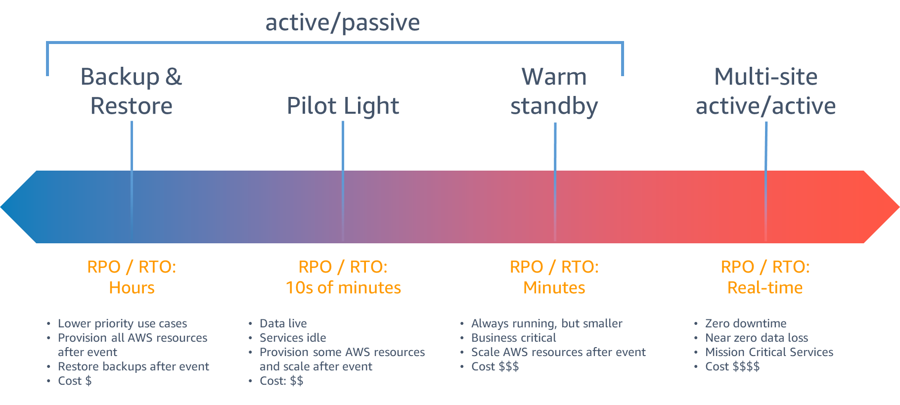
The recovery strategy this blog post targets is a warm standby architecture: two Kubernetes clusters are continuously running and able to accept traffic, as long as your services are horizontally scalable you can keep the secondary failover region at lower capacity and scale up in the event of a disaster.
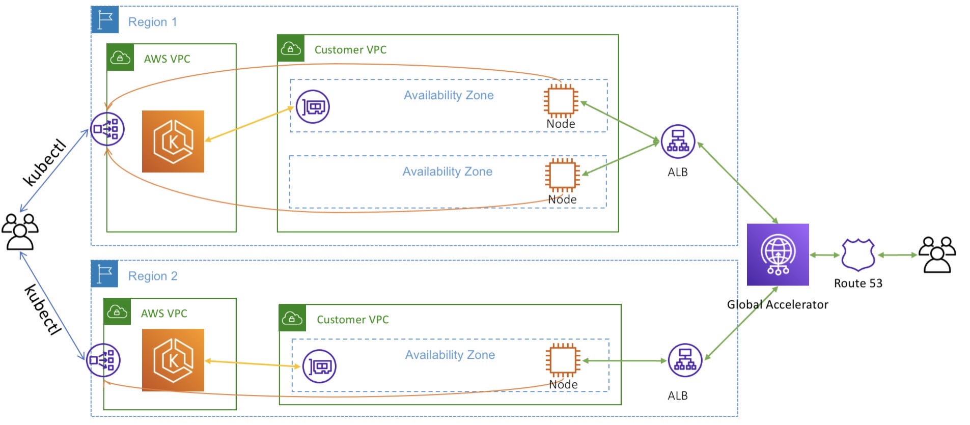
The overall architecture we will be implementing in this post is to
deploy two EKS clusters in two regions: one in us-east-1 and the other in
us-west-2. Each cluster is deployed to a separate VPC. To properly direct
traffic to the correct primary cluster, we use AWS Global Accelerator.
Global Accelerator provides a pair of globally unique IP addresses that
serve as the entry point into our application. Global Accelerator can be
configured to direct a percentage of traffic to one cluster at a time.
Implementation
To simplify the explanation, we can use the eksctl
tool to easily provision EKS clusters in two regions. Go ahead and
install eksctl using the instructions
available. If you are on macOs, you can
use homebrew
brew tap weaveworks/tap
brew install weaveworks/tap/eksctl
Creating the clusters
Our multi-region deployment uses two different clusters in two different
regions. To keep things simple (and cost-effective), we declare a node
group with only one EC2 instance as the node using the following
configuration for eksctl.
apiVersion: eksctl.io/v1alpha5
kind: ClusterConfig
metadata:
  name: ${EKS_CLUSTER}
  region: ${AWS_REGION}
managedNodeGroups:
  - name: main-ng
    instanceType: m5.large
    desiredCapacity: 1
    privateNetworking: true
Using the envsubst command, we can set the appropriate environment
variables before creating the cluster. Go ahead and create a cluster in
us-east-1 and us-west-2.
us-east-1 cluster
AWS_REGION=us-east-1 EKS_CLUSTER=sookocheff-us-east-1 envsubst < eksconfig.yml | eksctl create cluster -f -
us-west-2 cluster
AWS_REGION=us-west-2 EKS_CLUSTER=sookocheff-us-west-2 envsubst < eksconfig.yml | eksctl create cluster -f -
Enabling IAM Roles for Service Accounts
In both clusters, we need to enable AWS IAM Roles to Kubernetes Service
Accounts. When enabled, EKS
uses an admission controller to inject AWS session credentials into pods
based on the annotation of the Service Account used by the pod. The
credentials will get exposed as AWS_ROLE_ARN and
AWS_WEB_IDENTITY_TOKEN_FILE environment variables. Recent versions of
the AWS SDK will automatically read these environment variables, so
nothing more needs to be done by any application running on a pod that
needs access to AWS services.
To set up the OIDC provider necessary for IAM-based service accounts, execute the following command for each cluster we created.
eksctl utils associate-iam-oidc-provider --cluster=<clusterName> --approve
Getting traffic to our cluster
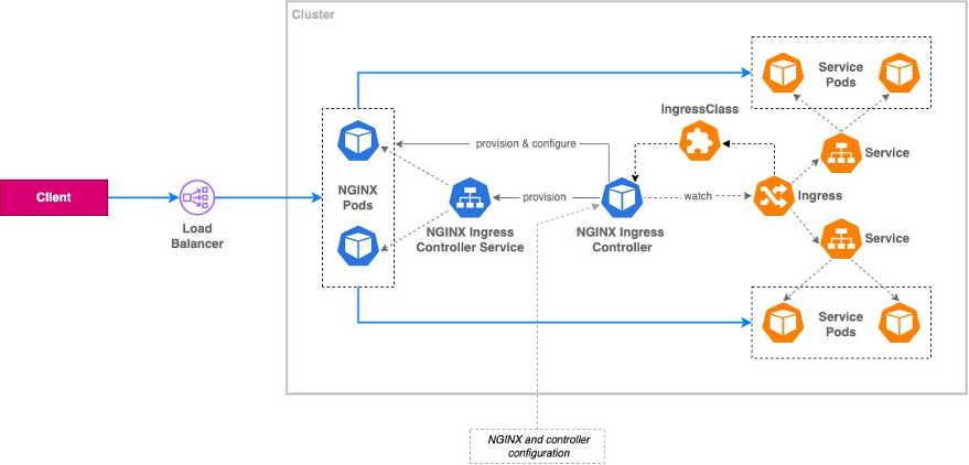
For our example cluster, we will deploy a load balancer outside of Kubernetes to direct traffic destined for Kubernetes pods using the AWS Load Balancer Controller. Using this controller, an AWS Elastic Load Balancer will be deployed in response to events in the Kubernetes control plane. Once traffic reaches our cluster, we direct it to Nginx Ingress Controller, which acts as a Layer 7 reverse proxy that exposes individual services in our cluster to external traffic. The following diagram from this blog post on exposing Kubernetes applications shows the overall architecture.
Setting up IAM Roles for the AWS Load Balancer
An IAM policy with the required permissions for the AWS Load Balancer Controller is available on Github, you can grab that policy directly from the repo:
curl -o iam_policy.json https://raw.githubusercontent.com/kubernetes-sigs/aws-load-balancer-controller/v2.4.7/docs/install/iam_policy.json
With the policy file in place, you can create the policy using the following command. Note that since IAM is a global service, this only needs to be done once to create the policy for both regions.
aws iam create-policy \
    --policy-name EksLoadBalancerControllerIAMPolicy \
    --policy-document file://iam_policy.json
We have the policy, now we need to create the Kubernetes Service Account
in each cluster that uses the policy. The following command does just
that, leveraging eksctl. Substitute EKS_CLUSTER with clusters created
earlier, and ACCOUNT_ID with your AWS account id. You can grab this
easily using aws sts get-caller-identity --query 'Account' --output text
eksctl create iamserviceaccount \
    --cluster=${EKS_CLUSTER} \
    --name=aws-load-balancer-controller \
    --namespace=kube-system \
    --attach-policy-arn=arn:aws:iam::${ACCOUNT_ID}:policy/EksLoadBalancerControllerIAMPolicy \
    --approve
Install the AWS Load Balancer Controller
With the correct service account in place, we can install the AWS Load Balancer Controller using helm.
First, add the EKS charts repo.
helm repo add eks https://aws.github.io/eks-charts
Then install the load balancer, referencing the service account we previously created. Remember to install the load balancer in each cluster we created.
helm install aws-load-balancer-controller eks/aws-load-balancer-controller \
    -n kube-system \
    --set clusterName=<cluster-name> \
    --set serviceAccount.create=false \
    --set serviceAccount.name=aws-load-balancer-controller
Install the Nginx Ingress Controller
The nginx Ingress Controller needs to configured with annotations that
allow the AWS Load Balancer Controller to route traffic to it. To set
these annotations, create the following file called values.yaml with
the appropriate annotations set. In this case, we change the Service type
to be LoadBalancer, and define the name for the load balancer that will
be used (in this case default-ingress). We make it internet-facing, so
we can access it, define its target type to be IP, and configure the
health check for the NGINX server it will route to.
controller:
  service:
    type: LoadBalancer
    annotations:
      service.beta.kubernetes.io/aws-load-balancer-name: default-ingress
      service.beta.kubernetes.io/aws-load-balancer-type: external
      service.beta.kubernetes.io/aws-load-balancer-scheme: internet-facing
      service.beta.kubernetes.io/aws-load-balancer-nlb-target-type: ip
      service.beta.kubernetes.io/aws-load-balancer-healthcheck-protocol: http
      service.beta.kubernetes.io/aws-load-balancer-healthcheck-path: /healthz
      service.beta.kubernetes.io/aws-load-balancer-healthcheck-port: 10254
With this file in place, we can deploy the nginx Ingress Controller using Helm:
helm upgrade -i ingress-nginx ingress-nginx/ingress-nginx \
    --namespace kube-system \
    --values values.yaml
Deploying the service
To test our setup, we can deploy an application to each region that simply prints the application name alongside the region that it resides in. For that, I use this simple Kubernetes Service and Deployment that uses the http-echo container to simply return HTTP with the region.
apiVersion: apps/v1
kind: Deployment
metadata:
  name: ${SERVICE_NAME}
  labels:
    app.kubernetes.io/name: ${SERVICE_NAME}
spec:
  selector:
    matchLabels:
      app.kubernetes.io/name: ${SERVICE_NAME}
  replicas: 1
  template:
    metadata:
      labels:
        app.kubernetes.io/name: ${SERVICE_NAME}
    spec:
      terminationGracePeriodSeconds: 0
      containers:
        - name: ${SERVICE_NAME}
          image: hashicorp/http-echo
          imagePullPolicy: IfNotPresent
          args:
            - -listen=:3000
            - -text=${SERVICE_NAME} | ${AWS_REGION}
          ports:
            - name: app-port
              containerPort: 3000
          resources:
            requests:
              cpu: 0.125
              memory: 50Mi
---
apiVersion: v1
kind: Service
metadata:
  name: ${SERVICE_NAME}
  labels:
    app.kubernetes.io/name: ${SERVICE_NAME}
spec:
  type: ClusterIP
  selector:
    app.kubernetes.io/name: ${SERVICE_NAME}
  ports:
    - name: svc-port
      port: 80
      targetPort: app-port
      protocol: TCP
Our resource definition takes two environment variables. The name of the
service (SERVICE_NAME), and the region that it is deployed to (AWS_REGION).
Switch the Kubernetes context to the first region in us-east-1, and
deploy the app.
SERVICE_NAME=first AWS_REGION=us-east-1 envsubst < service.yaml | kubectl apply -f -
Deploy the same app again using the us-west-2 Kubernetes context.
SERVICE_NAME=first AWS_REGION=us-west-2 envsubst < service.yaml | kubectl apply -f -
At this point, we have the same application deployed to both clusters.
Deploying an Ingress
To allow traffic external to the cluster to reach our services requires deploying an ingress. Our ingress is fairly simple, it routes a request matching a prefix to the service we just deployed.
apiVersion: networking.k8s.io/v1
kind: Ingress
metadata:
  name: default-ingress
spec:
  ingressClassName: nginx
  rules:
    - http:
        paths:
          - path: /first
            pathType: Prefix
            backend:
              service:
                name: first
                port:
                  name: svc-port
Deploy the ingress using this file. You may need to wait for up to ten minutes for the Elastic Load Balancer to be created before traffic is routable to your service.
kubectl apply -f ingress.yaml
You can test whether your ingress is working by retrieving the load balancer URL and making queries against it. The following command will retrieve the load balancer URL from the ingress resource.
export NLB_URL=$(kubectl get -n kube-system service/ingress-nginx-controller \
    -o jsonpath='{.status.loadBalancer.ingress[0].hostname}')
With the URL in hand, you can query your service. Repeat the process in both regions to see your ingress working for both EKS clusters.
curl ${NLB_URL}/first
We now have a service running in two clusters that are accessible from their own unique load balancers. Next, we tie these two clusters together using AWS Global Accelerator.
Deploying Global Accelerator
AWS Global Accelerator is a networking service that sends your user’s traffic through AWS’s global network infrastructure. In some cases, this can improve user experience because by offering an earlier access point onto Amazon’s networking infrastructure.
For our purposes, it also makes it easier to operate multi-regional deployments. Global Accelerator provides two static IP address that are anycast from AWS’s globally distributed edge locations. This gives you a single entry point into an application no matter how many regions it is deployed to.
Global Accelerator provides an improved experience over using DNS to failover traffic. DNS results are often cached by clients for unknown periods of time. With Global Accelerator, the DNS entry remains the same while allowing you to switch traffic between different endpoints. This eliminates any delays caused by DNS propagation or client-side caching of DNS results
Creating a Global Accelerator
A Global Accelerator consists of a few main components: listeners, endpoint groups, and endpoints.
A listener processes inbound connections from clients to Global Accelerator, based on the port (or port range) and protocol (or protocols) that you configure. TCP and UDP protocols. Each listener has one or more endpoint groups associated with it, and traffic is forwarded to endpoints in one of the groups.
Each endpoint group is associated with a specific AWS Region. Endpoint groups include one or more endpoints in the Region.
An endpoint is the resource within a region that Global Accelerator directs traffic to. Endpoints can be Network Load Balancers, Application Load Balancers, EC2 instances, or Elastic IP addresses.
AWS Global Accelerator can be created and configured from the command line. First, create the accelerator and take note of the ARN.
ACCELERATOR_ARN=$(aws globalaccelerator create-accelerator \
    --name multi-region \
    --query "Accelerator.AcceleratorArn" \
    --region us-east-1 \
    --output text)
Next, add a listener on port 80 for the TCP protocol. This configures Global Accelerator to listen for HTTP traffic.
LISTENER_ARN=$(aws globalaccelerator create-listener \
  --accelerator-arn $ACCELERATOR_ARN \
  --region us-west-2 \
  --protocol TCP \
  --port-ranges FromPort=80,ToPort=80 \
  --query "Listener.ListenerArn" \
  --output text)
The load balancers we created as part of our default ingress need to be registered as endpoints for the listener, so we can direct traffic to the correct location. Traffic is routed to one or more registered endpoints in the endpoint group. Using the command line, you can register both an endpoint group and endpoints within the group using the same command.
For both regions, repeat the following steps:
First, query AWS for the ARN of the load balancer matching our ingress we previously created.
export INGRESS_ARN=$(aws elbv2 describe-load-balancers \
    --region us-east-1 \
    --query "LoadBalancers[?contains(DNSName, 'default-ingress')].LoadBalancerArn" \
    --output text)
Next, create the endpoint group with an endpoint configured as the ingress load balancer we created.
ENDPOINT_GROUP_ARN=$(aws globalaccelerator create-endpoint-group \
  --region us-east-1 \
  --listener-arn $LISTENER_ARN \
  --endpoint-group-region us-east-1 \
  --query "EndpointGroup.EndpointGroupArn" \
  --output text \
  --endpoint-configurations EndpointId=$INGRESS_ARN,Weight=128,ClientIPPreservationEnabled=True)
When repeating these steps for the secondary region, set the traffic dial
to route 0% of traffic to the us-west-2 endpoint group.
ENDPOINT_GROUP_ARN=$(aws globalaccelerator create-endpoint-group \
  --region us-east-1 \
  --listener-arn $LISTENER_ARN \
  --endpoint-group-region us-west-2 \
  --query "EndpointGroup.EndpointGroupArn" \
  --traffic-dial-percentage 0 \
  --output text \
  --endpoint-configurations EndpointId=$INGRESS_ARN,Weight=128,ClientIPPreservationEnabled=True)
With this configuration, we have a single global accelerator configured
to send 100% of traffic to our cluster in us-east-1 and 0% of traffic
to our cluster in us-west-2.
Testing it out
To test out our configuration, we can send traffic to the DNS entry of the global accelerator.
GA_DNS=$(aws globalaccelerator describe-accelerator \
  --accelerator-arn $ACCELERATOR_ARN \
  --query "Accelerator.DnsName" \
  --output text)
We configured global accelerator to route 100% of traffic to the
us-east-1 region. When we make a request to the accelerator, it
responds with the region where the application was deployed.
❯ curl $GA_DNS/first
first | us-east-1
In the AWS console, if you set the accelerator’s traffic dial to route
100% of traffic to us-west-2 and 0% of traffic to us-east-1 after
a few moments you will see traffic directed to us-west-2 through the
same entry point.
❯ curl $GA_DNS/first
first | us-west-2
To simulate a disaster recovery scenario, you can delete the ingress rule and load balancer in the primary region. The health status in global accelerator will report as unhealthy and begin routing users to the healthy region.