There is no one-size-fits-all cellular network used across the world, and trying to understand how cellular technology works across all the different uses cases is difficult, if not impossible, in a short blog post. So, rather than trying to understand every possible standard, this article will focus solely on LTE networks. Fortunately, competing standards and implementations are roughly similar and we can extrapolate any lessons learned about LTE to other cellular networks without much difficulty.
The Long Term Evolution (LTE) Standard
LTE is a redesign of the 3G standard to satisfy the demand for low latency data transmission. The redesign includes:
- An IP address based core network
- A simplified network architecture
- A new radio interface
- A new modulation method
- Multiple input, multiple output radios (MIMO) for all devices
Together, these improvements lower latencies and increase throughput throughout the network. These improvements also imply that an LTE network is not a simple upgrade to an existing 3G network. LTE requires new hardware and operates on a separate spectrum from the 3G network.
One way that LTE simplifies the network architecture is by consolidating the logic for how a device connects to the network into a single component — the Radio Resource Controller. This component tracks the connection state of a device and allocates radio resources to a device so that it can send and receive data over the network. In LTE, the RRC is the “brains of the operation”.
The Radio Resource Controller (RRC)
Ethernet makes the assumption that a node is always connected to the network and can simply send or receive data at any time. With mobile, this assumption is flawed — keeping the radio active at all times is simply too taxing on the battery. Furthermore, a mobile network may have significantly more active users than a home network, increasing the possibility of a collision should everyone be sending or receiving data at the same time. The Radio Resource Controller (RRC) is a solution to these problems. The RRC is a central piece of infrastructure that schedules the connection between devices and the network. It schedules who uses the network, and when they can use it, allocates bandwidth to each user, mediates the signal power used to communicate, negotiates the power state of each device, and more.
The state of an LTE device on the network is decided by a state machine algorithm defined by the LTE specification and implemented by the RRC. Every LTE network uses the same state machine (but may vary the parameters that trigger a state change to fine tune their network). When a device is connected to the network, the RRC sets the device status to either idle or connected.

- RRC Idle
- Device radio is in a low-power state (<15 mW) and only listening to control traffic. No radio resources are assigned to the client within the carrier network. RRC Connected
- Device radio is in a high-power state (1000–3500 mW) while it either transmits data or waits for data, and dedicated radio resources are allocated by the radio network.
When the device is idle, it is only listening to control channel broadcasts, such as paging notifications of inbound traffic. When it is connected, the network has set aside dedicated radio resources for the device. An interesting consequence of this state machine assignment is that a device in the idle state cannot send or receive data — it first has to listen to broadcast control traffic from the RRC and request to be moved to the connected state. Once the device is in the connected state, there is a context (somewhat similar to a web browser session) established between the device and the network, and data can be transferred. After a timeout period where no data is sent or received, the device is transitioned back to the idle state.
When the radio is in the connected state, it requires a large amount of power. To use this power more efficiently, there are multiple possible sub-states a device can be in.
- Continuous reception
- The highest power state. Used when a network connection has been established and radio resources have been allocated to the device. Short Discontinuous Reception (Short DRX)
- A network connection has been established, but no radio resources have been allocated to the device. Long Discontinuous Reception (Long DRX)
- A network connection has been established, but no radio resources have been allocated to the device. The period to poll for new status updates is longer than Short DRX.
If a device is receiving or transmitting data, it will be in the continuous reception state. After it has been idle for a period of time, it is transitioned into a short DRX state. In this state, the network connection is still maintained but there are no specific radio resources assigned. If there is more data to receive or transmit, the RRC must allocate radio resources again for the device by sending control messages to the device and changing the state back to continuous reception. The long DRX state is identical to the short DRX state, except for that fact that it sleeps for a longer period of time before waking up to listen to control broadcasts. The long DRX state is triggered after the radio has been idle for a configurably long period of time. If the device remains in the long DRX state for a period of time, it transitions back to the idle state.
An important consequence of the timeout-driven radio state transitions, regardless of the generation or the underlying standard, is that it is very easy to construct network access patterns that can yield both poor user experience for interactive traffic and poor battery performance. In fact, all you have to do is wait long enough for the radio to transition to a lower-power state, and then trigger a network access to force an RRC transition!
LTE Carrier Architecture
The RRC is the key component connecting a device to the cellular network, but how does data flow into and out of the network? To understand this, we need to look at the end-to-end carrier architecture. In broad strokes, the network architecture is divided into three parts, as in the following figure from High Performance Browser Networking:

The first portion of this figure is the Access Network, also called the E-UTRAN (short for UMTS Terrestrial Radio Access Network), which is responsible for connecting a physical device to the Core Network, also known as the Evolved Packet Core in an LTE deployment. The Core Network is then responsible for connecting the user’s device to external networks like the public Internet. To get a sense of how each of these architectural components work, the next few paragraphs will dive a little bit deeper into each.
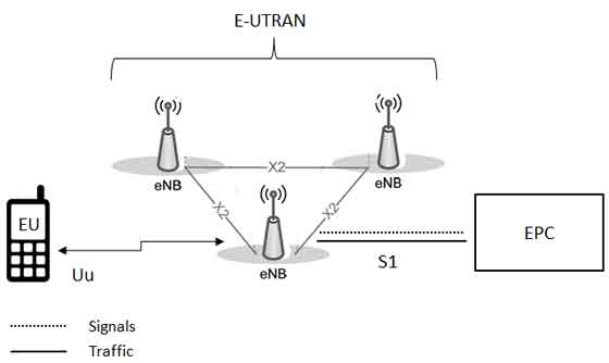
The E-UTRAN handles radio communication between a device and the Evolved Packet Core network. The only component in the E-UTRAN are cellular base stations, called eNodeB hosts. These base stations are responsible for maintaining the Radio Resource Controller state, and they perform all radio resource assignments for each active device in its broadcast area, called a cell. The eNodeB connected to a device controls all low-level operation of the device, such as handing the device over to a neighbouring base station as a user moves around in the physical world. The eNodeB also sends and receives all radio transmissions to the devices it is responsible for using the LTE modem interface on each device. The following figure shows a high level overview of the E-UTRAN network.
The Evolved Packet Core (EPC) is responsible for connecting the radio network to the public Internet. It performs traditional IP-switched data routing, and manages any network policies or accounting desired by the network operators. The EPC is divided into multiple components, as shown in the following figure:
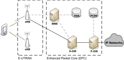
- The Packet Data Gateway (P-GW) is a public gateway connecting the mobile network to the public Internet. The P-GW communicates with the outside world and is the termination point for all mobile network connections that are destined for external endpoints. When a device is connected to the public Internet, the P-GW allocates the IP address for the device and does the appropriate network address translation to route traffic destined to that IP to the appropriate cellular device.
- The Policy Control and Charging Rules Function (PCRF) is typically deployed alongside the Packet Gateway. This component is responsible for policy control decision-making, such as packet filtering or enforcing a user’s data limit.
- The mobility management entity (MME) manages the state for every user on the network. MME is effectively a user management service, tracking the users’ location, their account, their billing status, and a bunch of other metadata for each user on the network. As a user moves throughout the network, base station location changes are propogated to the MME component.
- The Home Subscriber Service (HSS) is effectively a component of the MME service. It is a database of user data, and kept as a separate component of the network architecture because it is a legacy technology in use by older cellular networks like a 3G UMTS network.
- The serving gateway (S-GW) acts as a router, and forwards data between the base station associated with a user and the packet gateway. When data is received destined for an IP address, the serving gateway queries the MME component for the location of the user, and the S-GW routes the data to the appropriate cellular tower in the radio access network.
In a nutshell, the operation of an LTE network can be summarized as follows:
- Data arrives at the external packet gateway, which connects the core network to the public Internet.
- A set of routing and packet policies is applied at the packet gateway.
- Data is routed from the public gateway to one or more serving gateways, which act as mobility anchors for the devices within the radio network.
- A user database service performs the authentication, billing, provisioning of services, and location tracking of each user on the network.
- Once the location of the user within the radio network is determined, the data is routed from the serving gateway to the appropriate radio tower.
- The radio tower performs the necessary resource assignment and negotiation with the target device and then delivers the data over the radio interface.
End-to-End Packet Flow
To put it all together, we can look at how a packet flows through an LTE network. Imagine the case of a user waking up in the morning and browsing Facebook. The user requests a URL from the Internet. What happens?
First, the device has been asleep for the night, so it is in the RRC idle state. To wakeup from this state, the radio must synchronize with a nearby cellular base station by sending a request for radio resources. The RRC allocates the required resources to the device and the device is notified that it can move to the connected state. Now the user can transmit data at the rate and power specified by the RRC.
While a device is in the connected state, data can be sent directly to the device’s assigned cellular tower without any need to negotiate with the RRC. This remains true as long as the device is in a high power connected state.
Once a packet reaches a radio tower, it needs to be forwarded to the Evolved Packet Core before reaching the public Internet. In particular, the packet first arrives at the serving gateway (S-GW), which forwards the packet on to the packet data gateway (P-GW). The packet gateway records the internal IP address of the user’s device and acts as a proxy to the public Internet on the user’s behalf.
Once Facebook has received the request for a URL, it needs to send data back. Facebook has no knowledge of the user’s device and interacts only with the P-GW. The P-GW terminates the connection on behalf of the user and forwards the data on to the S-GW. The S-GW queries the MME to find out the exact cellular tower serving the user’s device and then forwards the data to the appropriate tower. The eNodeB at this tower then uses the knowledge it has of the user’s device state stored in the RRC to send the data to the device’s LTE modem.
An important caveat in all of this is that the user’s device may have gone idle at any point due to inactivity. If this is the case, the P-GW can still act as a proxy connected to the Internet and can receive data on behalf of the device — even if the device has its radio turned off. One the packet arrives at the S-GW and the device is idle, the MME sends a paging request to all cellular towers in the area, which broadcast a notification on a shared radio channel telling the device to restablish a radio context with the RRC to receive inbound data. The device finds out about these broadcasts by periodically waking to listen to control messages. After the device’s radio context has been restablished, the cellular tower notifies the MME, which in turn notifies the S-GW, which is now able to route the message to the correct radio tower. Finally, the tower sends the data to the device through the device’s LTE modem interface.
More References
Cellular networking is a complex topic, and this article provides only a brief overview of the architecture of an LTE network. If you want to learn more, there are several great resources to choose from: