To deliver real-time communication (RTC) from browser to browser requires a lot of technologies that work well together: audio and video processing, application and networking APIs, and additional network protocols that for real-time streaming. The end result is WebRTC — over a dozen different standards for the application protocols and browser APIs that enable real-time communication for the web.
The following figure, from webrtc.org, shows a high-level overview of the WebRTC technology stack. There is a lot going on here, and we can start to understand how WebRTC works by picking apart the individual pieces from this overview.
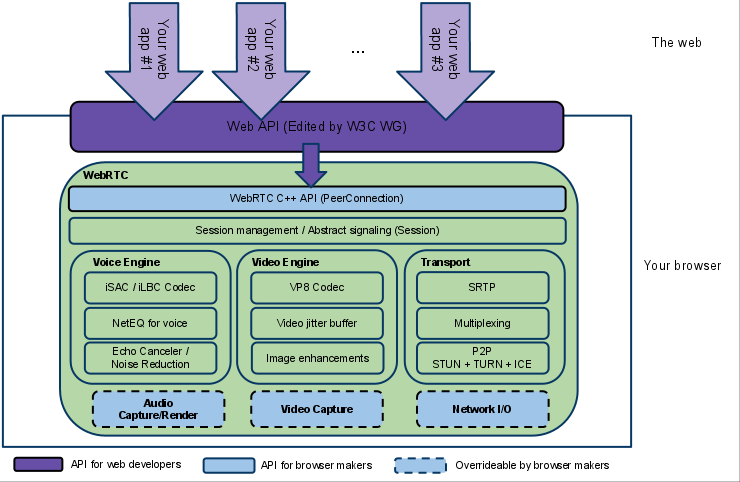
Web API
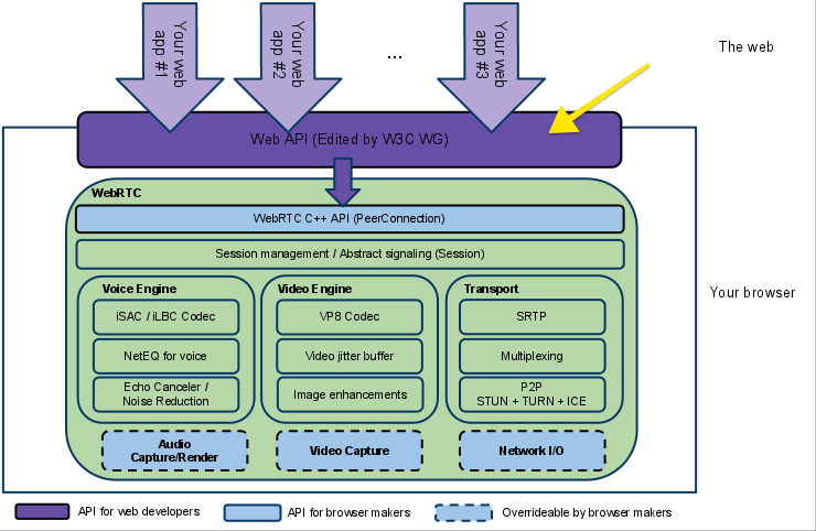
At the top of the technology stack is the WebRTC Web API, which is maintained by the W3C. The Web API is a JavaScript API that application developers use to create a real-time communication application in the browser. Although the Web API is undoubtedly interesting for application developers, it is not the focus of this article. If you want to learn more about how to build an application using WebRTC, refer to the Mozilla Developer Network documentation.
If you are interested in learning a bit more about how WebRTC works, our journey continues down the WebRTC stack.
WebRTC C++ API

The next level down is the C++ API for WebRTC that enables browser makers to implement the JavaScript-based WebAPI. This layer of the WebRTC stack allows browsers to implements the Peer Connection API, which manages the full lifecycle of establishing and maintaining a peer-to-peer connection between two browsers, and the Stream API, which manages delivery of individual real-time communication streams. These APIs encapsulate all of the connection management, setup, session state, and data delivery within simple interfaces for browser developers and is closely tied to the Session Management interface. If you want to learn more about the browser API, refer to the [WebRTC documentation][https://webrtc.org/native-code/native-apis/] as a starting point.
From here, WebRTC splits into three different verticals, one for voice processing, one for video processing, and a third for the connection management and transport.
VoiceEngine

The VoiceEngine is a framework for the browser to implement audio media capture, from the low-level capture of raw data from the sound card all the way up to transporting that data over the network. The VoiceEngine is composed of several different standards that handle different tasks. First, there are the audio codecs (iSAC, iLBC, and Opus). Second, echo cancellation algorithms. Third, a noise reduction component.
iSAC / iLBC / Opus Audio Codecs
There are three available audio codecs available to WebRTC implementers. Generally speaking, the Opus format is the most performant over widely varying network conditions, while iSAC and iLBC enjoy legacy support in VoIP applications. Implementers of the WebRTC standard are free to vary the audio codec used depending on application requirements and network conditions.
The internet Speech Audio Codec (iSAC) is a standard developed by Global IP Solutions. iSAC is already used by VoIP to provide a audio communications that adjust according to the bandwidth available (also called bandwidth-adaptive). iSAC is intended for wideband network conditions where bitrates may be low and packet loss, delay, or jitter as are common (these conditions are usually true over wide area networks).
The Internet low bit rate codec (iLBC) is a narrowband speech codec for VoIP and streaming audio defined in RFCs 3951 and 3952. iLBC is well suited to poor network conditions with limited bitrates and is more rubust to lost speech frames — audio quality gracefully degrades as network conditions detiorate.
Opus is a lossy audio coding format standardized in RFC 6716, and incorporates technology already deployed by Skype. Opus is a flexible codec that can handle a wide range of audio applications, including Voice over IP, videoconferencing, in-game chat, and even remote live music performances. It can scale from low bitrate narrowband speech to very high quality stereo music.
Acoustic Echo Canceler (AEC)
The Echo Canceler is a signal processor that removes any acoustic echo from the voice. This is a needed component because WebRTC was developed with end-user browser-based communication in mind. This means that most WebRTC users will have an integrated camera, speaker and microphone where the output from the speaker will be picked up by the active microphone. Without echo canceling, you would end up with feedback and an unusable audio stream.
Noise Reduction (NR)
Noise Reduction is another signal processing component developed to deal with the common conditions of WebRTC and VoIP deployments. Specifically, computers emit a lot of background noise like the spinning of a fan, or the hum of an electrical wire. Noise Reduction reduces these noises to enhance the quality of the audio stream.
VideoEngine
VideoEngine, as the name would suggest, provides much the same functionality as AudioEngine, only tailored to streaming video. VideoEngine also is similarly intended to take a raw video capture from the device and prepare it for transport over the web.
VP8
VP8 is the video codec taken from the WebM, which is tasked with developing free and open video formats for the web. VP8 is well suited for WebRTC because it is designed for low latency. One of the greatest benefits of VP8 is that it is completely unencumbered by patents after Google provided an irrevocable release of the codec under a Creative Commons licence.
Raw video is bandwidth intensive, and the key functionality that VP8 provides is video compression.
Video jitter buffer
The jitter buffer helps conceal packet loss. The jitter buffer works by collecting and storing incoming media packets in a buffer, and decides when to pass them along to the decoder and playback engine. It makes that decision based on the packets it has collected, the packets it is still waiting for and the timing required to playback the media.
Image enhancements
Any image enhancements are dependent on the WebRTC implementation. Typically, the VideoEngine will remove any video noise from the image captured by the web cam.
Transport
Once we have audio and video data processed and encoded, we need to send it over the network. This is handled by the Transport component of the WebRTC architecture, the most important part of which is the Real-Time Protocol that delivers an adaptive stream of data over UDP.
RTP — The Real-Time Protocol
UDP provides the backbone to build real-time communication applications. UDP provides a thin wrapper over basic IP delivery, and while this thin layer allows you eke out the best possible performance from your application, in most cases it is simply too thin to be useful — UDP is just too simple of a protocol to use directly for WebRTC. In particular, we need some additional logic for negotiating the connection parameters of the stream, handling encryption, and some basic forms of flow control to avoid overloading the network. To address these issues, WebRTC layers three additional protocols on top of UDP:
- Datagram Transport Layer Security (DTLS) is used to negotiate the secret keys for encrypting media data and for secure transport of application data.
- Secure Real-Time Transport (SRTP) is used to transport audio and video streams.
- Stream Control Transport Protocol (SCTP) is used to transport application data.
Datagram Transport Layer Security (DLTS)
HTTP-based traffic is typically secured using TLS, which would be a perfect choice for WebRTC if it weren’t for UDP — TLS requires reliable and in-order delivery. To address this gap, WebRTC leverages DLTS, which provides the same security guarantees as TLS, but works over UDP. In fact, DLTS is designed to be very similar to TLS, with a few modifications to make it work for UDP.
Each TLS connection is established using an initial handshake sequence that must be done in the correct order. UDP doesn’t offer any delivery or ordering guarantees and the only way to fix this is to enforce ordering of packets during the initial setup of the secure connection. DLTS does this by adding an offset and sequence number to each packet in the handshake, and then adding a timeout based retry mechanism to ensure that any lost packets are retransmitted. In effect, DLTS re-implements some of the features of TCP — at least for the duration of the initial connection setup.
Secure Real-Time Transport (SRTP)
Once a secure connection is established, we can begin sending data over the network. Here, WebRTC reuses existing transport protocols developed for VoIP technology: SRTP and SRTCP.
SRTP, defined in RFCs [3550][rfc-3550] and 3711, provides a standard header that can help the clients process the stream by synchronizing audio to video, and adjusting for out of order or lost data where necessary.
 0                   1                   2                   3
 0 1 2 3 4 5 6 7 8 9 0 1 2 3 4 5 6 7 8 9 0 1 2 3 4 5 6 7 8 9 0 1
+-+-+-+-+-+-+-+-+-+-+-+-+-+-+-+-+-+-+-+-+-+-+-+-+-+-+-+-+-+-+-+-+
|V=2|P|X|  CC   |M|     PT      |       sequence number         |
+-+-+-+-+-+-+-+-+-+-+-+-+-+-+-+-+-+-+-+-+-+-+-+-+-+-+-+-+-+-+-+-+
|                           timestamp                           |
+-+-+-+-+-+-+-+-+-+-+-+-+-+-+-+-+-+-+-+-+-+-+-+-+-+-+-+-+-+-+-+-+
|           synchronization source (SSRC) identifier            |
+=+=+=+=+=+=+=+=+=+=+=+=+=+=+=+=+=+=+=+=+=+=+=+=+=+=+=+=+=+=+=+=+
|            contributing source (CSRC) identifiers             |
|                             ....                              |
+-+-+-+-+-+-+-+-+-+-+-+-+-+-+-+-+-+-+-+-+-+-+-+-+-+-+-+-+-+-+-+-+
Two highlights from this header are the sequence number, which enables the receiver to detect and account for out-of-order delivery of media data, and the timestamp, that allows audio and video to be synchronized,
Whereas SRTP is used to distribute data, a separate stream is used to handle session management and control: SCTP.
Stream Control Transport Protocol (SCTP)
SCTP, defined in RFC 4960, is used to deliver application data that isn’t part of the real-time stream. SCTP is actually an interesting compromise that can be configured to meet the requirements of UDP or TCP, depending on the needs of the application. That is, SCTP can optionally provide in-order and guaranteed delivery, should the application using WebRTC choose to use it. SCTP provides similar services as TCP, but because it is tunneled over UDP and is implemented for us by the WebRTC protocol, it offers a much more powerful API: in-order or out-of-order delivery, configurable reliability guarantees, and multiplexing of data over the same connection.
STUN / TURN / ICE
Many browser-based APIs rely on the existing HTTP handshake to set up a connection (XHR, WebSocket, Server Sent Events). WebRTC, on the other hand, typically routes connections between individual home computers. This network architecture means that two parties in a WebRTC session are often hidden behind many layers of NATs, routers, and other Internet hardware. Within this environment, we need a method to gather the IP address and port of the computer we want to talk to. WebRTC leverages some of the existing protocols developed for routing UDP traffic for this task: STUN , TURN, and ICE.
STUN — Session Traversal Utilities for NAT
Session Traversal Utilities for NAT (STUN) is a protocol that serves as a tool for other protocols in dealing with Network Address Translator (NAT) traversal.
— [RFC 5389 — Session Traversal Utilities for NAT (STUN)][rfc5389]
STUN is one protocol for dealing with NAT devices that handle UDP traffic. STUN doesn’t handle NAT. Rather, it is a tool that NAT can use to determine the IP address and port allocated to an application. To use STUN, a client must connect to a STUN server that aids in discovering the client’s coordinates. The following figure, from [RFC 5389][rfc5389] shows a sample deployment of STUN.
                               /-----\
                             // STUN  \\
                            |   Server  |
                             \\       //
                               \-----/


                          +--------------+             Public Internet
          ................|     NAT 2    |.......................
                          +--------------+


                          +--------------+             Private NET 2
          ................|     NAT 1    |.......................
                          +--------------+


                              /-----\
                            //  STUN \\
                           |    Client |
                            \\       //               Private NET 1
                              \-----/
In this figure, the STUN client is behind two NAT devices that broker communication through private networks. The STUN server resides in the public Internet. To facilitate communication of UDP through NAT devices, STUN clients make a binding request to STUN servers. The binding request made to the STUN server traverses any NAT devices. The NAT devices will modify the source IP and port of the packet, and when the STUN server receives the request it will appear as though the request is from the NAT device. The STUN server returns the response to the client with a copy of the NAT device’s address. The STUN client receiving this response inspects this data to determine the coordinates that the NAT advertises for client requests. Now, the client application using STUN knows its public IP address and port and can use this data when sending requests to peers. Peers can respond to the correct IP address.
TURN — Traversal Using Relays around NAT
This specification defines a protocol, called TURN (Traversal Using Relays around NAT), that allows the host to control the operation of the relay and to exchange packets with its peers using the relay.
— [RFC 5766 — Traversal Using Relays around NAT (TURN)][rfc5766]
TURN, like STUN, requires a publicly addressable server. Whereas a STUN server aids a client in discovering its IP and port, a TURN server acts as a bridge between any NAT devices and clients using UDP. In this configuration, clients communicate with the TURN server only. The following figure, from [RFC 5766][rfc5766], shows a deployment of a TURN server and the IP address and port combinations advertised to peers at each stage of communication.
                                        Peer A
                                        Server-Reflexive    +---------+
                                        Transport Address   |         |
                                        192.0.2.150:32102   |         |
                                            |              /|         |
                          TURN              |            / ^|  Peer A |
    Client's              Server            |           /  ||         |
    Host Transport        Transport         |         //   ||         |
    Address               Address           |       //     |+---------+
   10.1.1.2:49721       192.0.2.15:3478     |+-+  //     Peer A
            |               |               ||N| /       Host Transport
            |   +-+         |               ||A|/        Address
            |   | |         |               v|T|     192.168.100.2:49582
            |   | |         |               /+-+
 +---------+|   | |         |+---------+   /              +---------+
 |         ||   |N|         ||         | //               |         |
 | TURN    |v   | |         v| TURN    |/                 |         |
 | Client  |----|A|----------| Server  |------------------|  Peer B |
 |         |    | |^         |         |^                ^|         |
 |         |    |T||         |         ||                ||         |
 +---------+    | ||         +---------+|                |+---------+
                | ||                    |                |
                | ||                    |                |
                +-+|                    |                |
                   |                    |                |
                   |                    |                |
             Client's                   |            Peer B
             Server-Reflexive    Relayed             Transport
             Transport Address   Transport Address   Address
             192.0.2.1:7000      192.0.2.15:50000     192.0.2.210:49191
In this figure, the TURN client and the TURN server are separated by a NAT, with the client on the private side and the server on the public side. The client knows the address of the TURN server through DNS or configuration and sends traffic to the server, the TURN server is then responsible for routing the traffic to the peer on behalf of the client.
ICE — Interactive Connectivity Establishment
This document describes a protocol for Network Address Translator (NAT) traversal for UDP-based multimedia sessions established with the offer/answer model. This protocol is called Interactive Connectivity Establishment (ICE). ICE makes use of the Session Traversal Utilities for NAT (STUN) protocol and its extension, Traversal Using Relay NAT (TURN).
[RFC 5245 — Interactive Connectivity Establishment (ICE)][rfc5245]
ICE is designed to establish communication sessions for UDP traffic using the best possible tunnel it can find: a direct connection if possible, STUN if there is a failure with direct connect, and TURN as a last resort.
The basic idea behind ICE is that a client may have a number of different IP addresses, depending on how it connects to the Internet: the address of the directly attached network device, an address assigned by a NAT device, or an address assigned by a TURN server. Each of these addresses has the potential to communicate with peers on the Internet, but it can be difficult to establish which of these addresses is the correct one to use and which won’t work. ICE is responsible for discovering which pair of addresses should be used for communicating between peers by systematically trying all possible communication pairs until it finds one that works.
Signaling and Session Negotiation
Before we can even use STUN, TURN, or ICE, we need to find out if the peer is reachable and wants to establish the connection. However, the other peer may not be listening for incoming packets, so how do we notify it of our intent? WebRTC solves this problem using an abstract session management interface that can use one of several existing signaling standards, depending on the application.
Rather than dive too deep into specfics, it is instructive to see an example: Skype. As a Skype user, if you want to make a Skype call you first have to login to Skype. This connects you to Skype’s signaling servers, which states your intention to have a video call and your availability. When another Skype user wants to connect with you, Skype uses the existing information it has about both peers to establish a connection over UDP using the technologies we’ve already discussed.
More References
WebRTC is a combination of many different technologies and building blocks, making it a fairly complex system. This article provided a brief overview of WebRTC. If you want to learn more, there are several great resources to choose from:
- High Performance Browser Networking
- WebRTC 1.0: Real-time Communication Between Browsers
- WebRTC Architecture
- WebRTC API
- RFC 3350 — RTP: A Transport Protocol for Real-Time Applications
- RFC 3711 — The Secure Real-Time Transport Protocol
- RFC 3951 — Internet Low Bit Rate Codec (iLBC)
- RFC 3952 — Real-time Transport Protocol (RTP) Payload Format for internet Low Bit Rate Codec (iLBC) Speech
- RFC 4566 — SDP: Session Description Protocol
- RFC 4960 — Stream Control Transport Protocol
- RFC 5245 — Interactive Connectivity Establishment (ICE)
- RFC 5389 — Session Traversal Utilities for NAT (STUN)
- RFC 5405 — Unicast UDP Usage Guidelines for Application Designers
- RFC 5766 — Traversal Using Relays around NAT (TURN)
- RFC 6347 — Datagram Transport Layer Security Version 1.2
- RFC 6716 – Definition of the Opus Audio Codec
- RFC 7874 — WebRTC Audio Codec and Processing Requirements