
It’s a dangerous business, Frodo, going out your door.
Kubernetes and public cloud infrastructure introduce a few layers of abstraction between users and our services. This article unravels some of those layers to help understand what, exactly, happens between the time a user makes a request to a Kubernetes service running in AWS and when the user receives a response. It’s helpful to start by framing a request in terms of the network boundaries involved, so let’s start there.
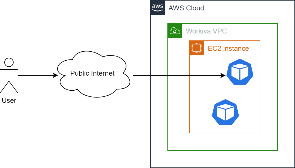
The preceding diagram shows a simplified view of a request originating from a User and arriving at a Kubernetes Pod running in AWS. The key challenge in routing traffic across these boundaries is network address translation. The public Internet has a different address space from a Virtual Private Cloud (VPC), and the subdivision of a VPC between private and public subnets requires translation to map between the two. Once we get into Kubernetes, we need to translate between the IP addresses of EC2 instances and those of individual Kubernetes Pods. To bridge the gap between all of the different address spaces that sit in the middle of a client and your service requires components with knowledge of those gaps and the means to fill them. How does this all happen? Let’s trace the path of an HTTP request to find out. We will start by breaking down an HTTP request to look at how packets reach the VPC, then how they reach the Kubernetes cluster, and follow that with an explanation of how a packet reaches the correct Kubernetes Pod running on an EC2 instance.
DNS Resolution
Home is now behind you, the world is ahead!
The namespace of internet domains is structured as an inverted tree with root nameservers at the top. This structure allows any nameserver to use a single piece of information — the location of a root nameserver — to find any other domain on the internet and translate that domain name into an IP address.
The root nameservers are the authoritative nameservers for all top-level domains. That is, given a query about any domain name, the root nameservers can provide the names and addresses of the authoritative nameservers for the top-level domains. In turn, the top-level nameservers can provide the list of authoritative nameservers for the second-level domains, and so on. In this recursive fashion, every time a nameserver is queried, it will either return the data for the domains it is authoritative for, or it will return information that is closer to the correct answer.
The following diagram from Amazon’s Route 53 documentation gives an overview of how recursive and authoritative DNS services work together to route an end user to your website or application.
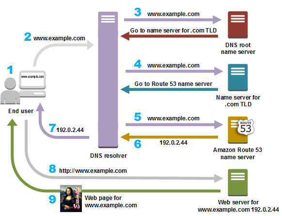
- A user opens a web browser, enters www.example.com in the address bar, and presses Enter.
- The request for www.example.com is routed to a DNS resolver, which is typically managed by the user’s Internet service provider (ISP), such as a cable Internet provider, a DSL broadband provider, or a corporate network.
- The DNS resolver for the ISP forwards the request for www.example.com to a DNS root name server. The root name server responds with the authoritative namerservers for the .com top-level domain (TLD)aut
- The DNS resolver for the ISP forwards the request for www.example.com again, this time to one of the TLD name servers for .com domains. The name server for .com domains responds to the request with the names of the nameservers that are associated with the example.com domain. In this example, those nameservers are implemented using Amazon Route 53.
- The DNS resolver for the ISP chooses an Amazon Route 53 name server and forwards the request for www.example.com to that name server.
- The Amazon Route 53 name server looks in the example.com hosted zone datafile for the www.example.com record, gets the associated value, such as the IP address for a web server, 192.0.2.44, and returns the IP address to the DNS resolver.
- The DNS resolver for the ISP finally has the IP address that the user needs. The resolver returns that value to the web browser. The DNS resolver also caches (stores) the IP address for example.com so that it can respond more quickly the next time someone browses to example.com.
- The web browser sends a request to the IP address that it got from the DNS resolver.
- The web server or other resource at 192.0.2.44 returns the web page for www.example.com to the web browser, and the web browser displays the page.
The example resolution we’ve used to convert the www.example.com domain into
the 192.0.2.44 IP address is fairly convoluted. To improve access speeds,
namservers typically cache query results to help speed up successive queries. In
our example, we can assume that a user makes a request to your domain name, and
that DNS resolution returns the correct IP address to reach your VPC. We now move
on to connecting that VPC to a Kubernete’s cluster.
Getting to Kubernetes
“Go back?” he thought. “No good at all! Go sideways? Impossible! Go forward? Only thing to do! On we go!”
Once DNS resolution is successful, the user request is routed to the public-facing IP address of your VPC. We can now start working on the problem of routing the request that reaches the VPC to the Kubernetes cluster.
To allow traffic to enter our VPC, we attach an Internet Gateway. An Internet Gateway is a logical connection between an Amazon VPC and the Internet. The Internet Gateway exposes resources within a public subnet to the Internet by providing a target for the VPC’s route table that we can direct internet-routable traffic to and by performing network address translation (NAT) for any instances that have been assigned public IP addresses. In following diagram, the public subnet is associated with a route table that directs all internet-bound traffic to an internet gateway, enabling communication with the Internet through a public Elastic IP on the EC2 instance.
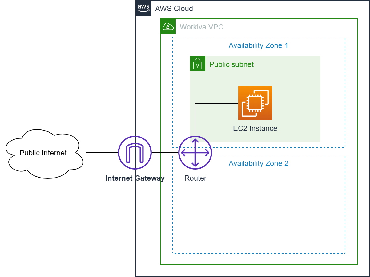
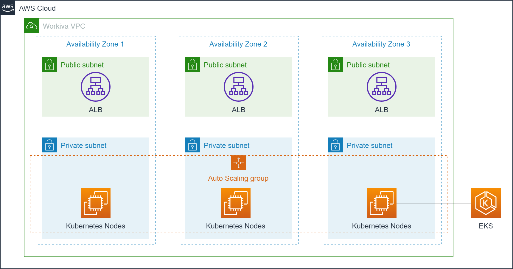
In AWS, a Kubernetes cluster runs within a VPC that is divided into availability zones. Each availability zone is further divided into a public and private subnet. Every Kubernetes Node (EC2 instance) lives in the private subnet and is assigned a private IP address that is accessible from other Nodes within the private subnet using AWS elastic network interfaces. To expose these Nodes to the public Internet, we place an Application Load Balancer (ALB) in each public subnet and make this Internet accessible by attaching a public IP address to the ALB and adding a DNS entry that resolves to the load balancers. The next figured shows the final deployment of Kubernetes in a Virtual Private Cloud, which closely matches the AWS reference architecture for EKS.
From a Kubernetes Node to your Pod
The road goes ever on and on.
Using the Internet Gateway we can route traffic reaching our VPC from the public Internet to the Application Load Balancers in the public subnet. With this in place, we still have the task of getting traffic to the correct Kubernetes Pods running within those EC2 instances. There are a few different ways to solve this problem, but Kubernetes makes opinionated choices about how Pods are networked to simplify the experience for application developers. In short, all Pods must be addressable with a unique IP address, without requiring Pods to do any network address translation. As a developer, this means you can treat Pods as individually addressable entities and everything “just works”. More specifically, Kubernetes requires three properties to be true and requires the network where Kubernetes is running to satisfy these properties:
- all Pods can communicate with all other Pods using an IP address
- all Nodes can communicate with all Pods using an IP address
- the IP that a Pod sees itself as is the same IP that others see it as
How Kubernetes implements this is a long subject worthy of a different blog post, but we can simplify the discussion by focusing on the problem of getting traffic to your Kubernetes Pod after it reaches the private subnet.
The following diagram provides more detail of the path an external request takes between the Application Load Balancer, an EC2 instance, and a Pod.
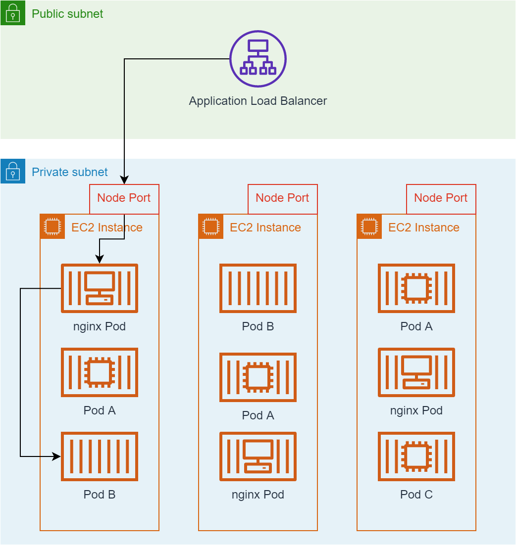
In this figure, the Application Load Balancer (ALB) is an Amazon managed EC2 instance placed in the public subnet. The ALB provides a stable endpoint (IP address) for external traffic to access. Requests reaching the ALB are load balanced across all EC2 instances in the cluster. The application load balancer knows nothing about the containers and services running on each EC2 instance. Rather, it simply distributes traffic to the set of EC2 instances that make up the Kubernetes cluster through an open port on the EC2 instance. Within the EC2 instance, an ingress controller implemeneted using nginx is aware of the services deployed in Kubernetes and their ingress rules and can route traffic to the correct Kubernetes Pods based on these ingress rules.
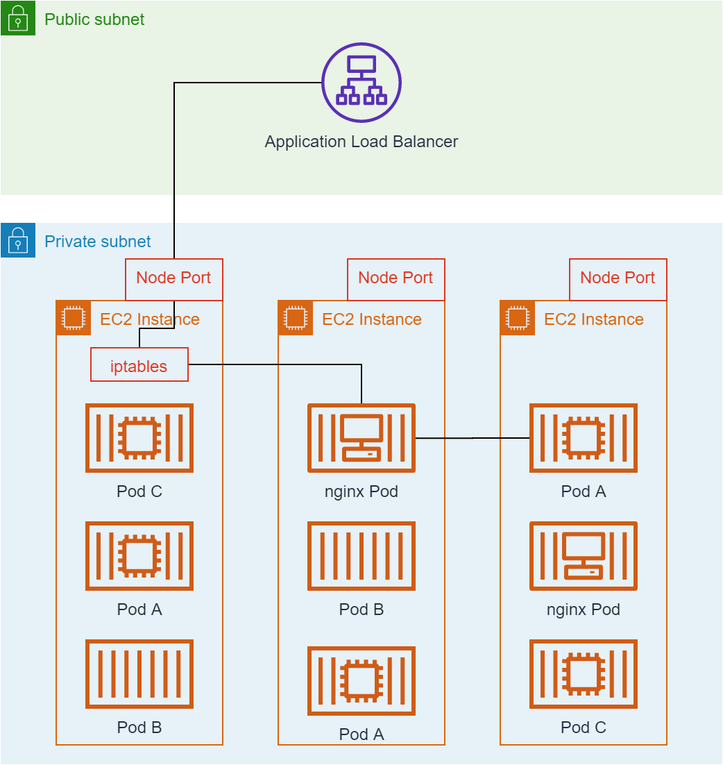
The nginx ingress controller is a Kubernetes service like any other, and it may
be deployed by Kubernetes on a subset of the available Nodes. The Application
Load Balancer is not container aware and simply routes the request to a random
EC2 instance which may not contain an nginx pod. iptables rules installed by
Kubernetes direct the request to an EC2 instance running the nginx ingress
controller as in the following figure. Full detail about how Kubernetes manages
iptables rules for an EC2 instance can be found in the guide to Kubernetes
networking.
There and Back Again
Sam: “‘There and Back again, a Hobbit’s Tale by Bilbo Baggins’ and ‘The Lord of the Rings by Frodo Baggins.’ You finished it!”
Frodo: Not quite. There’s room for a little more.
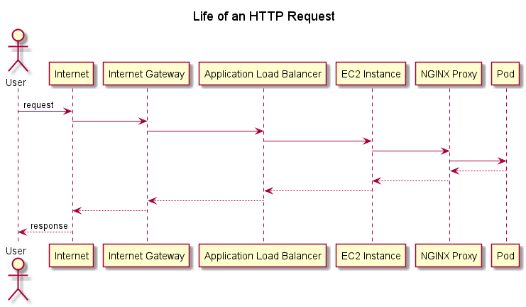
We’ve covered a lot of ground, but we now have enough detail to capture the life of a request from the time it reaches our Virtual Private Cloud within AWS to the time it reaches your Kubernetes Pod (and, of course, back again). The following diagram shows a sequence diagram of everything that happens during this journey if the request reaches an EC2 instance running an nginx proxy without requiring redirection through iptables rules.
As you can see from this post, a lot of different components are required to take even a simple HTTP request from a user’s browser to your service running as a Pod in Kubernetes. Although there is seemingly a lot of complexity in this arrangement, both the VPC and the Kubernetes deployment follow the best practices defined by AWS.
It is difficult to cover all of these components in depth in a short blog post. If you want to learn more, consider the following resources and consult the AWS documentation.