The Network Time Protocol (NTP) is a system for synchronizing the clocks of hosts and clients across the Internet. NTP is a protocol intended to synchronize all computers participating in the network to within a few milliseconds of Coordinated Universal Time (UTC). The core of the protocol is NTP’s clock discipline algorithm that adjusts the local computer’s clock time and tick frequency in response to an external source — such as another trusted NTP server, a radio or satellite receiver, or a telephone modem. A core problem in NTP is establishing the trust and accuracy of nodes in the NTP network. This is done through a combination of selection and filtering algorithms to choose from the most reliable and accurate peer in the synchronization network.
An argument can be made that the Network Time Protocol (NTP) is the longest running, continuously operating, distributed application on the Internet, with roots that can be traced back to 1979. The first documentation of the protocol was made available in 1981 as Internet Engineering Note series 173 IEN-173. Since then, it has evolved into Network Time Protocol Version 4, documented in RFC 5905 and ported to almost every client and server platform available today. NTP is running on millions of servers and clients across the world to keep accurate time on devices throughout the Internet.
NTP Network Architecture
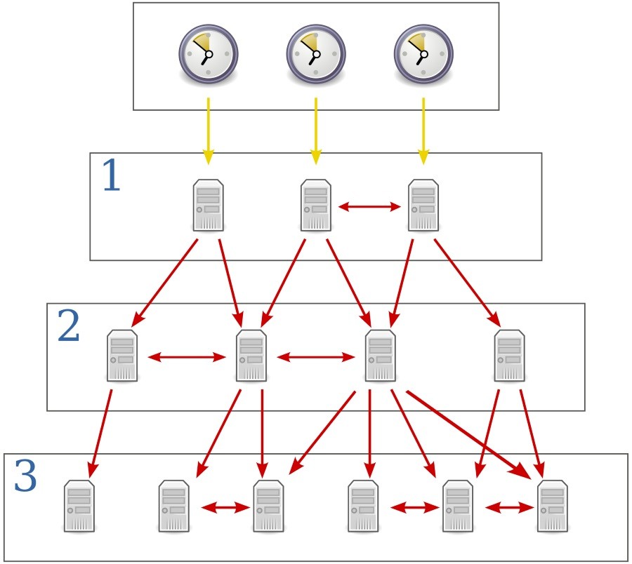
NTP uses a hierarchical network architecture that forms a tree structure. Each level of this hierarchy is called a stratum and is assigned a number starting with zero representing reference hardware clocks. A level one server is synchronized with a level zero server, and this relationship continues so that a server synchronized to a stratum \( n \) server runs at stratum \(n + 1\). The stratum number therefore represents the distance from an accurate reference clock. In general, the stratum of a node in the server is an indication of quality and reliability but this is not always the case; it is common to find stratum three time sources that are higher quality than other stratum two time sources.
Wikipedia has a good set of definitions for the different stratum that I’ve provided here with slight modification:
- Stratum 0
- These are high-precision timekeeping devices such as atomic clocks, GPS or other radio clocks. They generate a very accurate time signal that is directly connected to a connected computer. Stratum 0 devices are also known as reference clocks. NTP servers cannot advertise themselves as stratum 0.
- Stratum 1
- These are computers that are directly attached to stratum 0 devices. Their system time is synchronized to within a few microseconds of their attached devices. Stratum 1 servers may peer with other stratum 1 servers for sanity check and backup. They are also referred to as primary time servers.
- Stratum 2
- These are computers that are synchronized over a network to stratum 1 servers. Often a stratum 2 computer queries several stratum 1 servers and selects the most accurate time representation from them. Stratum 2 computers may also peer with other stratum 2 computers to provide more stable and robust time for all devices in the peer group.
- Stratum 3
- These are computers that are synchronized to stratum 2 servers. They employ the same algorithms for peering and data sampling as stratum 2, and can themselves act as servers for stratum 4 computers, and so on.
And this hierarchy continues up to stratum 15. The following figure depicts the hierarchical nature of the NTP system. Reference clocks at the top of the hierarchy are accurate time pieces and stratum 1 are computers directly attached to those time pieces. From there, increasing strata numbers indicate where each computer synchronizes time data from.
Within the NTP network, clients poll one or more servers at an interval to retrieve updated timestamp information.
The Local Clock Model
To make the NTP system as accurate and reliable as possible requires first an accurate and reliable local clock on host systems. For most purposes, the local clock is assumed to be a quartz crystal clock, which is a typical digital timepiece used in watches and computers. When a voltage is applied to the crystal it causes it to change shape; when the voltage is removed the crystal returns to its original shape (generating a small amount of voltage in the process). This change and return of shape happens at a stable frequency that can be adjusted during the manufacturing process. Once set, the crystal can maintain the frequency over long periods of time.
The local computer system uses the frequency that crystal oscillates at to increment the logical clock of the computer. Since the crystal oscillates at a pre-defined rate, the computer system can use this rate as a model of time. Quartz is accurate enough that it can maintain time within a few milliseconds per day. Over time however, these imperfections of a few milliseconds per day can accumulate, making the clock inaccurate. Enter NTP. NTP adjusts these inaccuracies at periodic intervals using corrections that are received by more accurate time servers. For hosts requiring the highest reliability, the computer is attached to a local hardware clock such as an atomic clock and receives time information directly from that attached clock.
The Phase and Frequency Locked Loop (PLL/FLL)
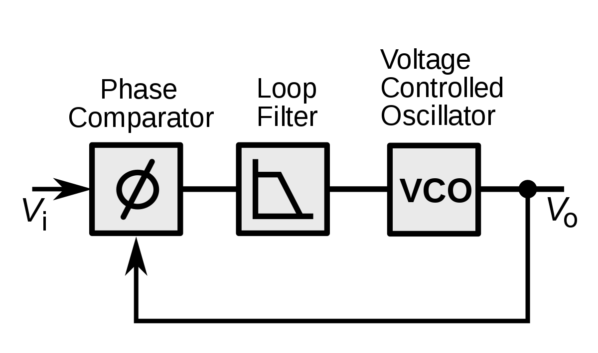
A phase-locked loop or PLL is any control system that generates an output signal whose phase is related to the phase of an input signal. The simplest version of a PLL is an electronic circuit consisting of a variable frequency oscillator and a phase detector that operate in a continuous feedback loop. The oscillator generates a periodic signal, and the phase detector compares the phase of that signal with the phase of the input periodic signal, adjusting the oscillator to keep the phases matched.
The following figure provides a more in-depth example.
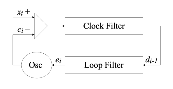
In the figure, \(x_i\) represents the reference timestamp from a reliable source and \(c_i\) the local timestamp. Both timestamps are at the \(i\)th update. The difference between these timestamps \(x_i - c_i\) is the input offset, which is processed by the clock filter. The filter recorded the most recent offsets and selects one from the set as the output offset to change the local clock with. The loop fliter is then used to produce the correction required for the local clock oscillator. If a correction is required, the local clock is gradually skewed to the correct value so that the clock shows smooth time indications and so that time values are monotonically increasing.
An alternative to a PLL is an FLL, which operates on the same principles but adjusts frequency rather than phase. Evidence shows that PLL usually works better when network jitter is the dominant factor for clock drift, and FLL works better when the natural wander of an oscillator is the dominant factor for clock drift. NTP v4 uses a combination of both a PLL and an FLL and combines those factors into a clock local adjustment.
A completely exhaustive explanation of the PLL/FLL algorithm in NTP requires 90 pages of documentation, but the overall ideas can be summarized fairly succinctly.
An NTP client receives time data from one or more connected servers and uses that time data to compute a phase or frequency correction to apply to the local clock. If the time correction is only a slight change, the correction is applied gradually (called slewing) in order to avoid clock jumps. If the local clock is off by a large amount, the adjustment may be applied all at once.
The adjustment to the local clock is called the clock discipline algorithm and it is implemented similar to the simple PLL feedback control system. The following diagram, from the presentation Network Time Protocol (NTP) General Overview, shows the basic overview of the process:
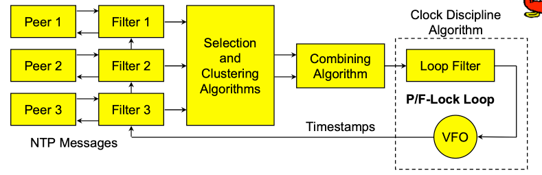
Here, an NTP client is connected to three NTP servers and receives timestamp data from all of them. Having multiple servers act as NTP peers provides some redundancy and diversity to the system. The clock filters select the statistically best time offset from the previous eight time samples received by the client, and the selection and clustering algorithms further narrow the dataset by pruning outliers from the result set. The combining algorithm then computes a weighted average of the time assets.
The output of this first process serves as the input to the PLL/FLL loop. The loop itself continuously adjusts the local clock phase and frequency in response to the input given from the filtered and averaged set of NTP servers.
The Clock Synchronization Algorithm
During typical operation, an NTP client regularly polls one or more NTP servers to receive updated time data. Upon receipt of new data, the client computes the time offset and round-trip delay from the server as in the following figure.
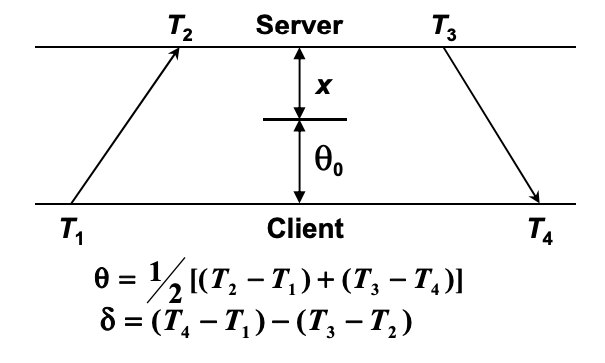
The time offset \( \theta \), the difference in absolute time between the two clocks, is defined mathematically by
$$ {\displaystyle \theta =\left\vert {\frac {(t_{2}-t_{1})+(t_{3}-t_{4})}{2}}\right\vert .} $$
More intuitively, the offset calculation is the absolute time difference between the two clocks time it takes for packets to transmit between the client and the server.
Using the time data, we can also calculate the network delay \( \delta \):
$$ {\displaystyle \delta ={(t_{4}-t_{1})-(t_{3}-t_{2})} .} $$
where,
- \(t1\) is the client’s timestamp of the request packet transmission,
- \(t2\) is the server’s timestamp of the request packet reception,
- \(t3\) is the server’s timestamp of the response packet transmission and
- \(t4\) is the client’s timestamp of the response packet reception.
At the very heart of NTP are the algorithms used to improve the accuracy of the values for \( \theta \) and \( \delta \) using filtering and selection algorithms. The complexity of these algorithms varies depending on the statistical properties of the path between peers and the accuracies required. For example, if two nodes are on the same gigabit LAN, the path delays between messages sent between peers are usually within or below any required clock accuracies. In a case like this, the raw offsets delivered by the receive procedure can be used to directly adjust the local clock. In other cases, two nodes may be distributed widely over the Internet and the delay might be much larger than acceptable.
Clock Filtering Algorithm
There are a number of algorithms for filtering time-offset data to remove glitches that fall into roughly two broad categories: majority-subset algorithms and clustering algorithms. Majority-subset algorithms attempt to separate good subsets of data from bad subsets of data by comparing statistics like mean and variance to select the best clock from a population of different clocks. Clustering algorithms work, on the other hand, by removing outliers to improve the overall offset estimate for a clock given a series of observations.
The full implementation of NTP’s clock filtering algorithm is described fairly succinctly in the presentation NTP Architecture, Protocol and Algorithms.
Clock Selection Algorithm
Likely the single most important factor in maintaining high reliability within NTP is choosing a peer. Whenever an event comes in and new offset estimates are calculated for a peer, the peer selection algorithm is used to determine which peer should be selected as the clock source.
Within the NTP network, a key design assumption that helps with the selection algorithm is that accurate clocks are relatively numerous and can be represented by random variables narrowly distributed close to UTC, while erroneous clocks are relatively rare and can be represented by random variables widely distributed throughout the measurement space.
The peer selection procedure thus begins by constructing a list of candidate peers by stratum. To be included on the candidate list the peer must pass certain sanity checks. For example, one check requires that the peer must not be the host itself. Another check requires the peers must have reachability registers that are at least half full, which avoids using data from low quality associations or obviously broken implementations. If no candidates pass the sanity checks, the existing clock selection, if any, is cancelled and the local clock free-runs at its intrinsic frequency.
The list is then pruned from the end to be no longer than a maximum size, currently set to five. Starting from the beginning, the list is truncated at the first entry where the number of different strata in the list exceeds a maximum, currently set to two. This procedure is designed to favor those peers near the head of the candidate list, which are at the lowest stratum and lowest delay and presumably can provide the most accurate time.
The full implementation of NTP’s selection algorithm is also given in the presentation NTP Architecture, Protocol and Algorithms.
Clock Combining Algorithm
The combine algorithm is the simplest of the bunch: it computes the final clock offset by averaging the surviving clocks that have been filtered and selected to produce a final offset used for adjusting the clock using the PLL/FLL clock control system.
NTP Message Formats
An NTP timestamp records the number of standard seconds relative to UTC. UTC started measuring time on 1 January 1972. The conceptual NTP clock was set to 2,272,060,800.0 at this same point in time, which represents the number of standard seconds since 1 January 1972 (the start of UTC) and 1 January 1900 (the conceptual start of NTP time).
An NTP timestamp is encoded as a 64-bit unsigned number, where the first 32 bits encode the integer portion of the timestamp and the last 32 bits encode the fractional portion. This format allows for convenient multiple-precision arithmetic and easy conversion to other time formats as required. The 32 bits of precision of a timestamp provide about 232 picoseconds of accuracy, which is likely more than enough precision for practical applications over networked systems.
NTP hosts and clients exchange timestamp records by copying the current value of the local clock to a timestamp variable in response to an incoming NTP message. An NTP host parses the incoming message, sets the timestamp on the message, and returns it to the client.
     0 1 2 3 4 5 6 7 8 9 0 1 2 3 4 5 6 7 8 9 0 1 2 3 4 5 6 7 8 9 0 1
    +-+-+-+-+-+-+-+-+-+-+-+-+-+-+-+-+-+-+-+-+-+-+-+-+-+-+-+-+-+-+-+-+
    |LI | VN  |Mode |    Stratum     |     Poll      |  Precision   |
    +-+-+-+-+-+-+-+-+-+-+-+-+-+-+-+-+-+-+-+-+-+-+-+-+-+-+-+-+-+-+-+-+
    |                         Root Delay                            |
    +-+-+-+-+-+-+-+-+-+-+-+-+-+-+-+-+-+-+-+-+-+-+-+-+-+-+-+-+-+-+-+-+
    |                         Root Dispersion                       |
    +-+-+-+-+-+-+-+-+-+-+-+-+-+-+-+-+-+-+-+-+-+-+-+-+-+-+-+-+-+-+-+-+
    |                          Reference ID                         |
    +-+-+-+-+-+-+-+-+-+-+-+-+-+-+-+-+-+-+-+-+-+-+-+-+-+-+-+-+-+-+-+-+
    |                                                               |
    +                     Reference Timestamp (64)                  +
    |                                                               |
    +-+-+-+-+-+-+-+-+-+-+-+-+-+-+-+-+-+-+-+-+-+-+-+-+-+-+-+-+-+-+-+-+
    |                                                               |
    +                      Origin Timestamp (64)                    +
    |                                                               |
    +-+-+-+-+-+-+-+-+-+-+-+-+-+-+-+-+-+-+-+-+-+-+-+-+-+-+-+-+-+-+-+-+
    |                                                               |
    +                      Receive Timestamp (64)                   +
    |                                                               |
    +-+-+-+-+-+-+-+-+-+-+-+-+-+-+-+-+-+-+-+-+-+-+-+-+-+-+-+-+-+-+-+-+
    |                                                               |
    +                      Transmit Timestamp (64)                  +
    |                                                               |
    +-+-+-+-+-+-+-+-+-+-+-+-+-+-+-+-+-+-+-+-+-+-+-+-+-+-+-+-+-+-+-+-+
    |                                                               |
    .                                                               .
    .                    Extension Field 1 (variable)               .
    .                                                               .
    |                                                               |
    +-+-+-+-+-+-+-+-+-+-+-+-+-+-+-+-+-+-+-+-+-+-+-+-+-+-+-+-+-+-+-+-+
    |                                                               |
    .                                                               .
    .                    Extension Field 2 (variable)               .
    .                                                               .
    |                                                               |
    +-+-+-+-+-+-+-+-+-+-+-+-+-+-+-+-+-+-+-+-+-+-+-+-+-+-+-+-+-+-+-+-+
    |                          Key Identifier                       |
    +-+-+-+-+-+-+-+-+-+-+-+-+-+-+-+-+-+-+-+-+-+-+-+-+-+-+-+-+-+-+-+-+
    |                                                               |
    |                            dgst (128)                         |
    |                                                               |
    +-+-+-+-+-+-+-+-+-+-+-+-+-+-+-+-+-+-+-+-+-+-+-+-+-+-+-+-+-+-+-+-+
Some of the keys fields are described here:
- LI (Leap Indicator): Warns of an impending leap second to be inserted or deleted at the end of the current day.
- VN (Version Number): Identifies the present NTP version.
- Mode, Stratum, Precision: Indicate the current operating mode, stratum and precision
- Poll: Controls the interval between NTP messages sent by the host to a peer. The sending host always uses the minimum of its own poll interval and the peer poll interval.
- Root Delay/Dispersion: Indicate the estimated roundtrip delay and estimated dispersion, respective to the primary reference source.
- Reference ID, Reference Timestamp: Identify the reference clock and the time of its last update, intended primarily for management functions.
- Origin Timestamp: The time when the last received NTP message was originated, copied from its transmit timestamp field upon arrival.
- Receive Timestamp: The local time when the latest NTP message was received.
- Transmit Timestamp: The local time when the latest NTP message was transmitted.
The NTP state machine running on each host machine maintains state variables for each of the above quantities as well as recording the IP address and ports of the host and its peers, a timer recording the interval between transmitting NTP messages, a register recording if the peer is reachable or not, as well as data measuring the current and estimated measured delay and offset associated with each single observation.
NTP also tracks the current clock source which identifies the clock that is currently being used to track time and the local clock time derived from the logical clock on the host machine.
In normal client-server operation, a server receives a message with this format from a peer, and the server populates the message with updated timestamp data before sending it back to the peer.
Each NTP host also sets a reachability shift register for each peer they communicate with. Each time a message is received the lowest order bit in the register is set to one, and the remaining positions are shifted to the left. The peer is considered reachable if the register is not zero, that is, if the peer has sent at least one message in the last eight update intervals. Peers who are unreachable may have their state information cleared.
Recap
NTP is a system of clients and peers that communicate timestamp information in a hierarchical format where nodes closer to the root of the hierarchy are, in general, considered more accurate keepers of time than nodes lower down in the hierarchy. Each NTP host responds to incoming messages requesting time information and keeps an active peer association for each of the clients to track key information.
In response to receiving time information, an NTP peer runs a process that includes the selection, cluster, and combine algorithms that mitigate among the various servers and reference clocks to determine the most accurate and reliable candidates to synchronize the with clock. The selection algorithm uses Byzantine fault detection principles to discard the presumably incorrect candidates called “falsetickers” from the incident population, leaving only good candidates called “truechimers”. A truechimer is a clock that maintains timekeeping accuracy to a previously published and trusted standard, while a falseticker is a clock that shows misleading or inconsistent time. The cluster algorithm uses statistical principles to find the most accurate set of truechimers. The combine algorithm computes the final clock offset by statistically averaging the surviving truechimers.
Once an appropriate clock adjustment, the adjustment itself is processed by a phase-locked and frequency-locked loop.
Resources
This article provides an introduction to NTP, and should provided a good overview for someone wanting to learn more about the protocol. If you want to learn more, there are several great resources to choose from: